Step Into Action: Mastering the ESP32 with Stepper Motor Control
ESP32 & Hardware
At Pacific Custom Engineering LLC, we’re committed to empowering our customers with innovative engineering solutions.
This project was inspired by several customer requests for a “getting started” guide for the ESP32 we sell here.
Today, we’re excited to share a hands-on project using this versatile board to control a stepper motor with a DR8825 driver, a liquid crystal display (LCD), and a keypad.
Detailed in our latest GitHub repository, this setup is perfect for hobbyists and professionals looking to dive into custom automation.

Setup Overview
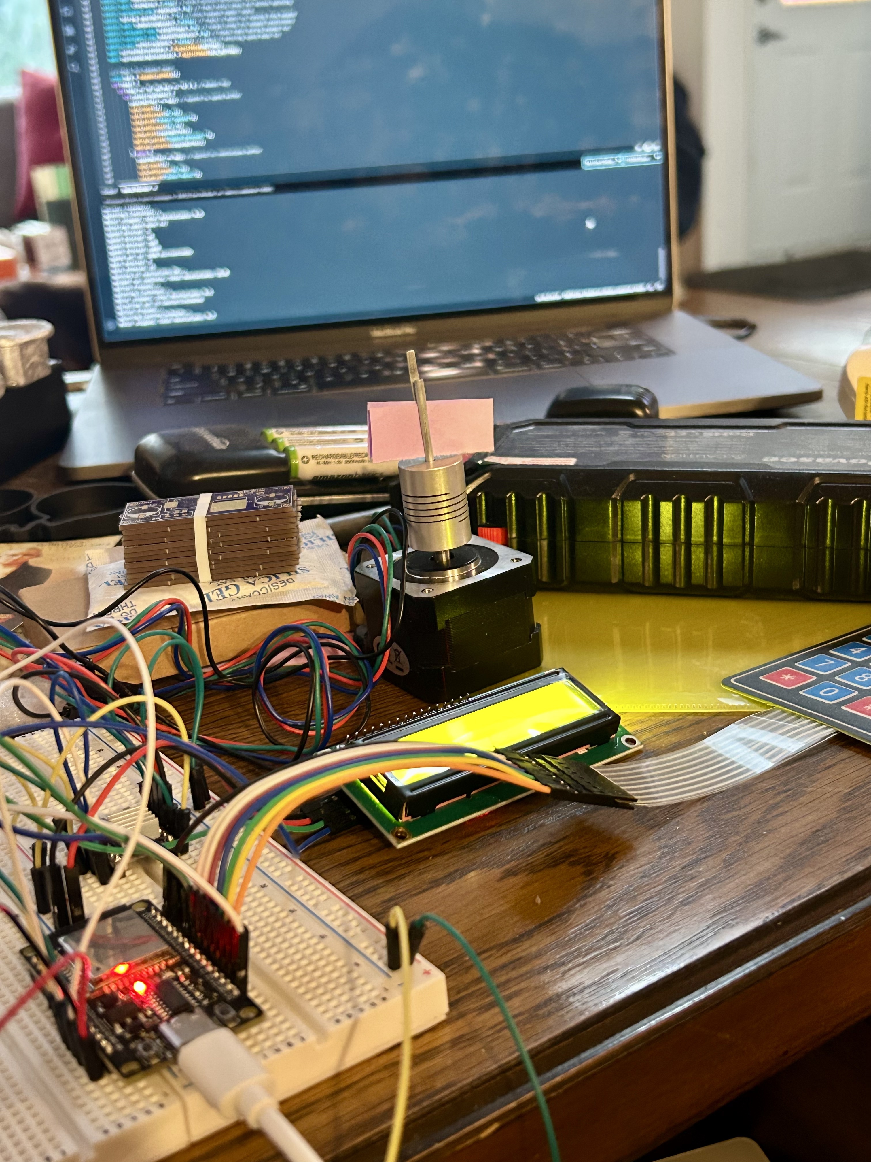
Our project features an ESP32 mounted on a breadboard, wired to a DR8825 driver that powers a stepper motor.
The LCD provides real-time feedback, currently displaying “Motor stopped” and “Revs: 4.7,” indicating the motor’s status and revolution count.
A keypad allows for manual input to control the motor.

The code defines the following pin assignments:
- ESP32 to DR8825 Stepper Driver:
- stepPin = 14: Controls the step signal to the DR8825.
- dirPin = 27: Controls the direction signal to the DR8825.
- enablePin = 26: Enables or disables the DR8825 driver (active low).
- sleepPin = 25: Puts the DR8825 into sleep mode (active low).
- ESP32 to LCD (Liquid Crystal Display):
- rs = 19: Register select pin for the LCD.
- en = 23: Enable pin for the LCD.
- d4 = 18: Data pin 4 for the LCD.
- d5 = 5: Data pin 5 for the LCD.
- d6 = 4: Data pin 6 for the LCD.
- d7 = 0: Data pin 7 for the LCD.
- ESP32 to Keypad:
- The code uses the Keypad library with a 4×4 keypad matrix. The row and column pins are defined as:
- rowPins[4] = { 13, 12, 15, 2 }: Rows connected to GPIO pins 13, 12, 15, and 2.
- colPins[4] = { 21, 22, 16, 17 }: Columns connected to GPIO pins 21, 22, 16, and 17.
- The code uses the Keypad library with a 4×4 keypad matrix. The row and column pins are defined as:
- Additional Notes:
- The code includes a button input on buttonPin = 32 to start or stop the motor.
Code Functionality Explained
The code, available on our GitHub repository here, offers a robust system for stepper motor control with the following key functionalities:
- Initialization: The ESP32 initializes the LCD to display motor status and revolution data, sets up the DR8825 driver with specific step and direction pins, and configures the keypad for input. This ensures all components are ready for operation upon startup.
- Motor Control: The DR8825 driver is programmed to control the stepper motor’s rotation. The code allows the motor to move a set number of steps, calculated to achieve a specific number of revolutions (e.g., 4.7 revolutions as shown). Users can start or stop the motor via keypad inputs, with the direction (clockwise or counterclockwise) potentially adjustable based on button presses.
- Keypad Interaction: The keypad serves as the user interface, with buttons mapped to specific commands. For instance, one button might start the motor, another stops it, and additional keys could adjust speed or direction. The code reads these inputs in a loop, updating the motor’s behavior accordingly.
- LCD Feedback: The LCD provides real-time updates, showing “Motor stopped” when idle and “Revs: X.X” when running, where X.X is the cumulative revolution count. This visual feedback helps users monitor the motor’s activity without additional tools.
- State Management: The code includes logic to track the motor’s state (running or stopped) and update the revolution count. It likely uses a variable to increment steps, converting them to revolutions based on the motor’s step angle (e.g., 200 steps per revolution for a standard stepper), and resets or adjusts this count as needed.
- Error Handling: Basic error checking might be present, such as ensuring the motor doesn’t exceed safe limits or handling invalid keypad inputs, though this would depend on the specific implementation.
This functionality makes the setup interactive and practical, serving as an excellent starting point for exploring the ESP32’s capabilities.
Summary of Pin Connections
|
Component
|
ESP32 Pin
|
Function
|
|---|---|---|
|
DR8825
|
14
|
Step
|
|
DR8825
|
27
|
Direction
|
|
DR8825
|
26
|
Enable
|
|
DR8825
|
25
|
Sleep
|
|
LCD
|
19
|
RS
|
|
LCD
|
23
|
Enable
|
|
LCD
|
18
|
D4
|
|
LCD
|
5
|
D5
|
|
LCD
|
4
|
D6
|
|
LCD
|
0
|
D7
|
|
Keypad (Rows)
|
13, 12, 15, 2
|
Row pins
|
|
Keypad (Cols)
|
21, 22, 16, 17
|
Column pins
|
|
Button
|
32
|
Start/Stop
|
Usage and Applications
This project can be adapted for various applications, from robotics and CNC machines to custom automation systems. The combination of the ESP32’s versatility, the DR8825’s precision, and the user-friendly interface of the LCD and keypad makes it a solid foundation for further experimentation.
Conclusion
We hope this project inspires you to dive into stepper motor control or explore other engineering challenges with our ESP32 development board. The full code is available on our GitHub, so feel free to download it, tweak it, and let us know your results. Have questions or ideas? Drop them in the comments or visit us at pacificcustomengineering.com for more projects and insights. Happy engineering!